
")
")
| Instructions for assembly | ||
|
|
||
|
|
• You can find all the exact conditions and specific technical information on the respective data sheets for the products. • The installation and connection of LEDlink products must be carried out in accordance with these instructions, free of voltage and only by specialist personnel. Electrostatic discharges and charges must also be avoided. Failure to comply may result in malfunctions, failures or a shortening of the service life. The power supplies in particular must be connected on the 230V side only by specialist personnel! • For outdoor use, it is important to only use products that also have a suitable IP protection. Connection points, open cable ends etc. must be protected against the ingress of moisture. This is best done using gel crimp connectors, heat shrink tubing or the like. • Since the LED chips are very sensitive, mechanical pressure on them must be avoided. • The power supply may only be implemented using power supplies that are intended for LED use. It is imperative to ensure that the correct output voltage is selected for the product to be supplied. (see data sheet). • Before assembly, the lamps must be checked for function, visible damage and correctness (correct light color, correct article, etc.). • The required power of the modules, stripes etc. must be calculated correctly and should not take up more than 80% of the nominal power of the electricity supplier. • It is important to ensure that the modules, stripes etc. are connected to the output of the power supply, taking into account the correct polarity. Open cable ends should always be insulated, especially for products for outdoor use, no moisture should get into the product via the open cables. • The arrangement or grid of the modules / stripes depends, among other things, on the installation depth and the material to be illuminated. (These installation recommendations can be found in the respective data sheets.) • Installation should take place on heat-repellent materials. The surface on which the modules, stripes, etc. are mounted should be smooth and dry, in addition, they must be cleaned and degreased thoroughly. In order to achieve perfect results, floor surfaces and side walls should be whitened. The light can thus be reproduced excellently. • In most cases, modules and stripes are equipped with 3M adhesive tapes. (see data sheet) These adhesive tapes are used for pre-installation and product alignment. They should not be seen as a temporary attachment measure. Especially outdoors, depending on the product, it should be secured separately with suitable mounting screws, mounting clips or mounting glue. • Checking whether the modules have been installed in the correct grid so that there is homogeneous illumination under the given conditions should be done before the final and temporary assembly. • During installation, the maximum number of modules fed in series must not be exceeded. (see data sheet) With LED stripes it is usually 5m, which may be fed in a maximum of in rows. (see data sheet) The modules or stripes should not be installed too far from the power supply. To select the correct cable cross-section from the cable "Power supply -> Module / Stripes", you will find a table below the text to analyze it. So that there are no tragic voltage drops, etc. • No liability is accepted as soon as LEDlink products are subsequently processed mechanically or chemically.
|
|
| Especially for LED stripes | ||
|
|
||
|
|
• You must not stretch, kink or choose a bending radius that is too narrow, as this can damage the conductor tracks. • The LED stripes may only be separated at the marked points. In the case of stripes with IP protection, it must be ensured after the separation that the open end is protected against the ingress of moisture. • Soldering the connections should also only be carried out by specialist personnel. • The soldering iron may only touch the connection pads as briefly as possible. (max. 280 ° C for approx. 5-10 seconds) Too much heat can damage the product and shorten the lifespan. • LED stripes are generally not resistant to chlorine, UV, salt water, solvents, alkalis and acids. Accordingly, all LED strips must be protected from direct sunlight and chemical additives (e.g. during cleaning). If it is a version with resistant properties, the technical data already indicates in the catalog / data sheet which specific properties are available. • Please note that the LED strip can expand or contract slightly when the temperature changes. This is not a product defect, but a normal physical process. This means that there can be a linear thermal linear expansion of approx. 1 cm per meter at a temperature change of 15 ° C. This additional length expansion must be taken into account in the planning for the LED stripe and the aluminum profile used. |
|
| Electrical scheme | ||
| LED MODULES | ||
|
The max number of modules that can be fed in series can be found in the respective data sheets. |
||
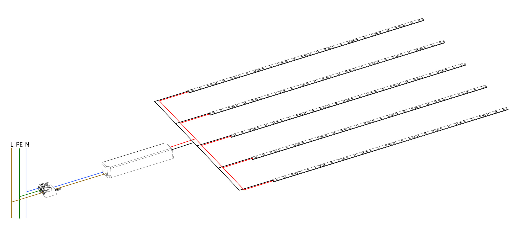
| LED STRIPES | ||
|
There may be max. 5 m of stripe connected in series. |
||
| RGB MODULE AND STRIPES | ||
 |
||

| Common problems | ||||
|
Problem |
potential cause | possible solution | ||
| All modules / stripes flash |
Overload by too much power for a too small power supply |
Check the max. 80% of the rated power from the power supply |
||
| LED’s light up weak |
Overload by too much power for a too small power supply Too many modules fed in series |
Check the max. 80% of the rated power from the power supply Check if too many modules are connected in series according to the data sheet |
||
|
Subareas does not light up Complete failure of the entire system |
Wackelkontakt, incorrectly clamped, electr. Short circuit Fault in the local power supply, power supply protection triggers short circuit |
Check connections between power supply and lamp, check polarity Check the fuse Turn input voltage once OFF and ON again Switch off the power and remove the short circuit |
||
|
Shading on the illuminating surface Shading since the lamp is lit in the |
Components such as a power supply, terminals or cables will cast shadows Module / Stripes badly attached / secured, thus no longer in the correct position |
Place the power supply wherever you want and attach the cables, etc. Module grid is not correct Reft the lamp and secure it properly |
||
|
|
||||